Criaremos um termômetro com Attiny85 e display binário através de seis LEDs. Utilizaremos apenas três pinos do microcontrolador para os seis LEDs, através da técnica de charlieplexing. O sensor de temperatura será o DHT11, comunicando com o Digispark Attiny85 através de um único fio.
O Digispark Attiny85 foi criado pelo grupo Digistump. Este grupo começou com uma campanha no Kickstarter, justamente do produto Digispark Attiny85. Hoje o grupo não existe mais, então a comunidade assumiu a manutenção do projeto. Isso porque o Attiny85 é uma plaquinha super útil, tem até USB.

Eu escolhi o Attiny85 para o projeto do termômetro binário justamente por ser pequeno, com baixo consumo de energia e com quantidade de pinos suficiente para o que eu preciso. Para também comprar a placa você pode acessar este link do Aliexpress. Aqui está como usar o Digispark Attiny85.
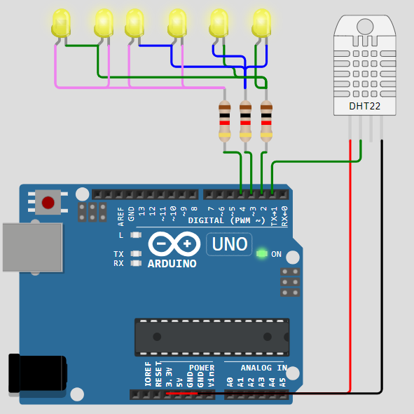
A ligação dos seis LEDs foi inspirada neste link, utilizando apenas três pinos do Attiny85. A imagem abaixo é apenas para referência.

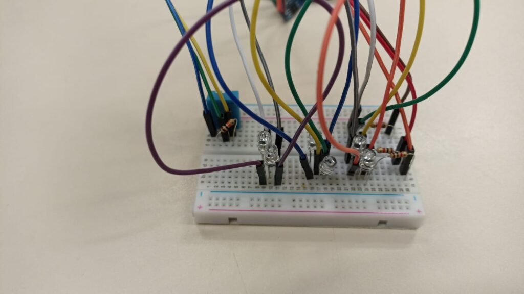
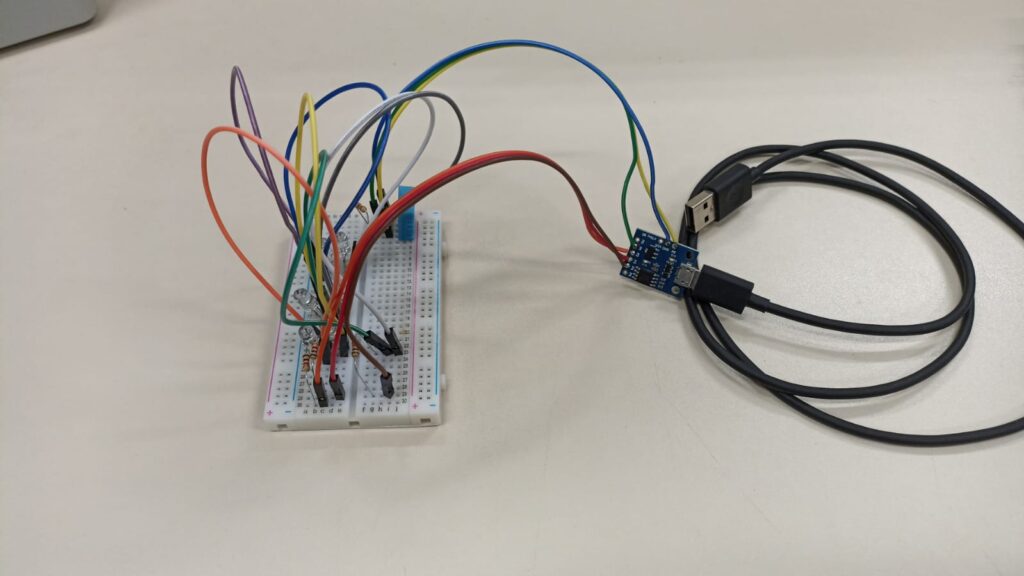
O primeiro protótipo do produto é visto abaixo, foi feito em protoboard.
O código
Todo o código do projeto está disponível aqui, feito para IDE do Arduino. O caminho a ser percorrido pela informação neste projeto é o seguinte:
- Leitura do sensor DHT11, retorna um float
- Conversão de float para int (inteiro)
- Conversão de int para binário (6 bit)
- Transferência da informação binária para as saídas correspondentes, através de charlieplexing
A mágica de converter de float para binário ocorre nas linhas abaixo, onde eu faço um laço FOR com seis passadas. em cada passada ocorre o arredondamento do valor de temperatura “t”, depois conversão para inteiro e depois conversão para bit. Onde i é a variável de controle dos bits.
for (int i = 0; i < 6; i++) {


      bitsresultados[i] = bitRead(int(round(t)), i); //This is where the magic happens, I get the "t" value (temperature),
      // round it, convert it to integer and extract every bit of its binary equivalent. The bits are then used to enter
      // each charlieplexed LED bit value

    }
Depois em outra parte do código ocorre a conversão de cada bit para seu valor correspondente no charlieplex. No exemplo abaixo eu ligo a saída 2 e desligo a 3 caso o bit 5 de bitsresultados[] for igual à 1. Neste caso a saída 4 é setada como entrada para não interferir nas outras duas.
if (digitoaentrar == 1 && passagem == 1) {
      if (bitsresultados[5] == 1) {
        pinMode(2, OUTPUT);
        pinMode(3, OUTPUT);
        pinMode(4, INPUT);
        digitalWrite(2, HIGH);
        digitalWrite(3, LOW);
      }
      digitoaentrar = 2;
    }
Eu não utilizo a função delay(), portanto o código não é bloqueante (ele não para/congela entre ações que deve tomar). Veja o código completo abaixo.
#include <DHT.h>
#include <DHT_U.h>

// Example testing sketch for various DHT humidity/temperature sensors
// Written by ladyada, public domain

// REQUIRES the following Arduino libraries:
// - DHT Sensor Library: https://github.com/adafruit/DHT-sensor-library
// - Adafruit Unified Sensor Lib: https://github.com/adafruit/Adafruit_Sensor

#include "DHT.h"


#define DHTPIN 1     // Digital pin connected to the DHT sensor
// Feather HUZZAH ESP8266 note: use pins 3, 4, 5, 12, 13 or 14 --
// Pin 15 can work but DHT must be disconnected during program upload.

// Uncomment whatever type you're using!
#define DHTTYPE DHT11   // DHT 11
//#define DHTTYPE DHT22   // DHT 22  (AM2302), AM2321
//#define DHTTYPE DHT21   // DHT 21 (AM2301)

int bitsresultados[6];
int passagem= 0;

// Variables used on this code
unsigned long time1;
unsigned long previousTime;
boolean enterFunction = true;
unsigned long time2;
unsigned long previousTime2;
boolean enterFunction2 = true;
//-----------------------

int digitoaentrar = 1;
float h;
float t;
float f;

// Connect pin 1 (on the left) of the sensor to +5V
// NOTE: If using a board with 3.3V logic like an Arduino Due connect pin 1
// to 3.3V instead of 5V!
// Connect pin 2 of the sensor to whatever your DHTPIN is
// Connect pin 3 (on the right) of the sensor to GROUND (if your sensor has 3 pins)
// Connect pin 4 (on the right) of the sensor to GROUND and leave the pin 3 EMPTY (if your sensor has 4 pins)
// Connect a 10K resistor from pin 2 (data) to pin 1 (power) of the sensor

// Initialize DHT sensor.
// Note that older versions of this library took an optional third parameter to
// tweak the timings for faster processors.  This parameter is no longer needed
// as the current DHT reading algorithm adjusts itself to work on faster procs.
DHT dht(DHTPIN, DHTTYPE);

void setup() {
  dht.begin();
  //Serial.begin(9600);
}

void loop() {

  time1 = micros();
  time2 = micros();
  if (enterFunction == true) {
    previousTime = time1;
    passagem++;
    // Start your code below
    //-----------------------


    if (digitoaentrar == 1 && passagem == 1) {
      if (bitsresultados[5] == 1) {
        pinMode(2, OUTPUT);
        pinMode(3, OUTPUT);
        pinMode(4, INPUT);
        digitalWrite(2, HIGH);
        digitalWrite(3, LOW);
      }
      digitoaentrar = 2;
    }
    if (digitoaentrar == 2 && passagem == 2) {
      if (bitsresultados[4] == 1) {
        pinMode(2, OUTPUT);
        pinMode(3, OUTPUT);
        pinMode(4, INPUT);
        digitalWrite(2, LOW);
        digitalWrite(3, HIGH);
      }
      digitoaentrar = 3;
    }
    if (digitoaentrar == 3 && passagem == 3) {
      if (bitsresultados[3] == 1) {
        pinMode(2, INPUT);
        pinMode(3, OUTPUT);
        pinMode(4, OUTPUT);
        digitalWrite(3, HIGH);
        digitalWrite(4, LOW);
      }
      digitoaentrar = 4;
    }
    if (digitoaentrar == 4 && passagem == 4) {
      if (bitsresultados[2] == 1) {
        pinMode(2, INPUT);
        pinMode(3, OUTPUT);
        pinMode(4, OUTPUT);
        digitalWrite(3, LOW);
        digitalWrite(4, HIGH);
      }
      digitoaentrar = 5;
    }
    if (digitoaentrar == 5 && passagem == 5) {
      if (bitsresultados[1] == 1) {
        pinMode(2, OUTPUT);
        pinMode(3, INPUT);
        pinMode(4, OUTPUT);
        digitalWrite(2, HIGH);
        digitalWrite(4, LOW);
      }
      digitoaentrar = 6;
    }
    if (digitoaentrar == 6 && passagem == 6) {
      if (bitsresultados[0] == 1) {
        pinMode(2, OUTPUT);
        pinMode(3, INPUT);
        pinMode(4, OUTPUT);
        digitalWrite(2, LOW);
        digitalWrite(4, HIGH);
      }
      digitoaentrar= 1;
      passagem= 0;
    }

    //-----------------------
    // End of your code
  }

  if (enterFunction2 == true) {
    previousTime2 = time2;

    // Reading temperature or humidity takes about 250 milliseconds!
    // Sensor readings may also be up to 2 seconds 'old' (its a very slow sensor)
    //h = dht.readHumidity();
    // Read temperature as Celsius (the default)

    t = dht.readTemperature();
    // Read temperature as Fahrenheit (isFahrenheit = true)
    //f = dht.readTemperature(true);

    for (int i = 0; i < 6; i++) {


      bitsresultados[i] = bitRead(int(round(t)), i); //This is where the magic happens, I get the "t" value (temperature),
      // round it, convert it to integer and extract every bit of its binary equivalent. The bits are then used to enter
      // each charlieplexed LED bit value

    }
   /* // Check if any reads failed and exit early (to try again).
    if (isnan(h) || isnan(t) || isnan(f)) {
      Serial.println(F("Failed to read from DHT sensor!"));
      return;
    }*/

    /*// Compute heat index in Fahrenheit (the default)
    float hif = dht.computeHeatIndex(f, h);
    // Compute heat index in Celsius (isFahreheit = false)
    float hic = dht.computeHeatIndex(t, h, false);*/


  }


  // The DELAY time is adjusted in the constant below >>
  if (time1 - previousTime < 990) { // 1 million microsencods= 1 second delay
    /* I have actually used 0.999990 seconds, in a trial to compensate the time that
       this IF function takes to be executed. this is really a point that
       need improvement in my code */
    enterFunction = false;
  }
  else {
    enterFunction = true;
  }
  if (time2 - previousTime2 < 4999990) { // 1 million microsencods= 1 second delay
    /* I have actually used 0.999990 seconds, in a trial to compensate the time that
       this IF function takes to be executed. this is really a point that
       need improvement in my code */
    enterFunction2 = false;
  }
  else {
    enterFunction2 = true;
  }

}
O diagrama esquemático
Simulei o projeto no Wokwi aqui, porém não funciona direito devido (eu imagino) à setar os pinos como entrada em tempo de execução. O diagrama esquemático também é visto abaixo, utilizando Arduino pois o Wokwi não tem Digispark Attiny85. Os pinos são os mesmos:
- Pino 1 para o sensor DHT11
- Pinos 2, 3 e 4 para os seis LEDs
O funcionamento
A leitura do DHT11 é feita a cada cinco segundos, enquanto cada LED é atualizado a cada 1 milissegundos. Isso para dar a impressão de que todos estão ligados ao mesmo tempo, enquanto na verdade apenas um é ligado por vez. Esse é o preceito básico do charlieplexing.
Abaixo uma imagem do circuito quase finalizado, mostrando como fazer a leitura da temperatura através do LEDs.
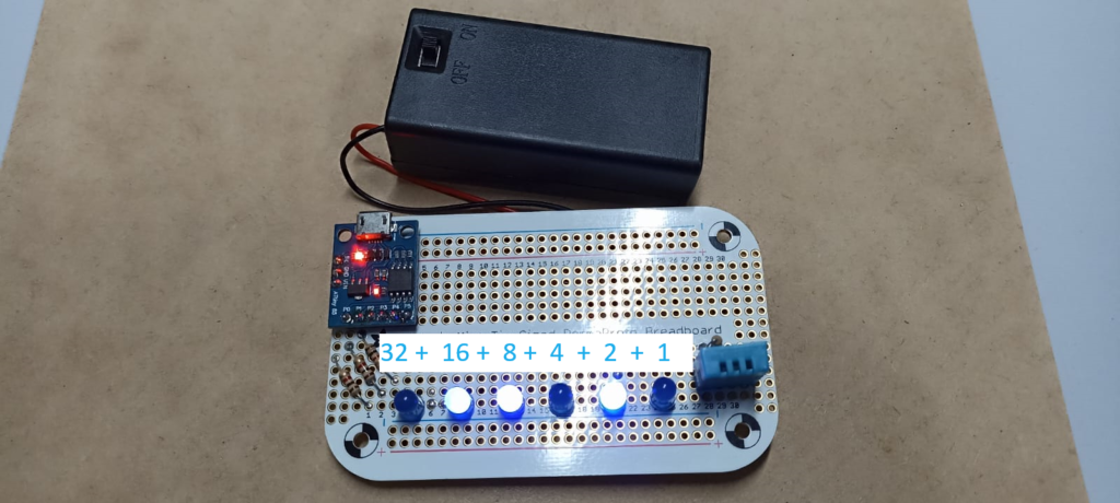
Na imagem acima o segundo (2^4), terceiro (2^3) e quinto (2^1) LEDs estão ligados, nos fornecendo 16+8+2= 26ºC. É bem simples ler em binário, basta somar o valor atribuído aos LEDs energizados.
Utilizei como alimentação do circuito uma bateria de 9V conectada diretamente ao pino VIN da placa Digispark Attiny85, sem filtragem nem nada.
Abaixo uma imagem do produto final, com o clip de bateria já colado á placa de protótipos. Lembrando que todo o código e diagrama esquemático estão disponíveis no meu Github, aqui.
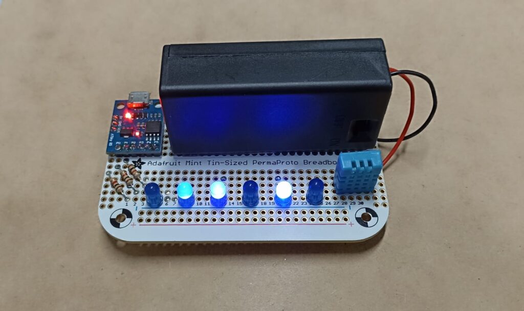
Obs: a temperatura mostrada acima também é 26ºC, já que os LEDs dois (2^4), três (2^3) e cinco (2^1) estão enerziados: 16+8+2= 26ºC.


Deixe um comentário